Mystery of Martian Icecaps Explained

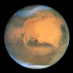
Hubble view of Mars, including its polar ice caps. Image credit: NASA. Click to enlarge.
NASA scientists have solved an age-old mystery by finding that Mars’ southern polar cap is offset from its geographical south pole because of two different polar climates.

Weather generated by the two martian regional climates creates conditions that cause the red planet’s southern polar ice to freeze out into a cap whose center lies about 93 miles (150 kilometers) from the actual south pole, according to a scientific paper included in the May 12 issue of the journal, Nature.

“Mars’ permanent south polar cap is offset from its geographic south pole, which was a mystery going back to the first telescopic observations of Mars,” said the paper’s lead author, Anthony Colaprete, a space scientist from NASA Ames Research Center, located in California’s Silicon Valley. “We found that the offset is a result of two martian regional climates, which are on either side of the south pole,” he said.

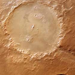
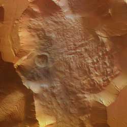
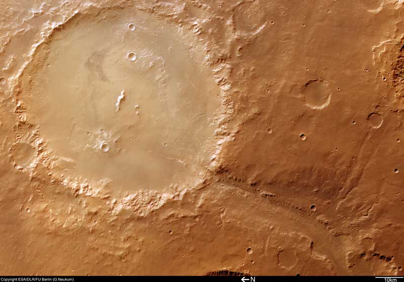
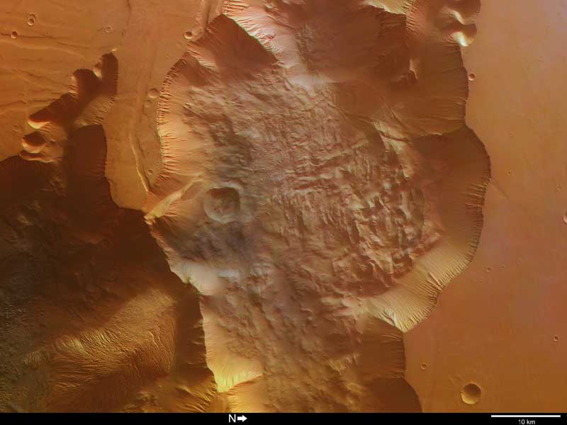
The scientists found that the location of two huge craters in the southern hemisphere of Mars is the root cause of the two distinct climates.

“The two craters’ unique landscapes create winds that establish a low pressure region over the permanent ice cap in the western hemisphere,” Colaprete explained.

Just as on Earth, low-pressure weather systems are associated with cold, stormy weather and snow. “On Mars, the craters anchor the low pressure system that dominates the southern polar ice cap, and keep it in one location,” Colaprete said.

According to the scientists, the low-pressure system results in white fluffy snow, which appears as a very bright region over the ice cap. In contrast, the scientists also report that ‘black ice’ forms in the eastern hemisphere, where martian skies are relatively clear and warm.

“The eastern hemisphere of the south pole region gets very little snow, and clear ice forms over the martian soil there,” Colaprete said. Black ice forms when the planet’s surface is cooling, but the atmosphere is relatively warm, according to scientists. “A similar process occurs on Earth when black ice forms over highways,” Colaprete explained.

Colaprete’s co-authors include Jeffrey Barnes, Oregon State University, Corvallis; Robert Haberle, also of NASA Ames; Jeffery Hollingsworth, San Jose State University Foundation, NASA Ames; and Hugh Kieffer and Timothy Titus, both from the U.S. Geological Survey, Flagstaff, Ariz.

Original Source: NASA News Release

Testing Strategies to Get Opportunity Unstuck

NASA engineers working with testing rover to get it unstuck. Image credit: NASA/JPL. Click to enlarge.
Mars rover engineers are using a testing laboratory to simulate specific Mars surface conditions where NASA’s rover Opportunity has spun its wheels in a small dune. Careful testing is preceding any commands for Opportunity to resume moving to get out of the dune and continue exploring.

The rover team at NASA’s Jet Propulsion Laboratory, Pasadena, Calif., has cooked up recipes combining various sandy and powdery materials for the best simulation on Earth of the dune where Opportunity dug itself in to wheel-hub depth last week. The team has not asked Opportunity to turn its wheels at all since the rover bogged down during a drive on April 26.

“We choose to proceed cautiously, so we don’t expect to begin actually driving out of the dune before next week, possibly later,” said Jim Erickson, rover project manager at JPL. “Both Opportunity and Spirit have already provided many more months of scientific exploration than anyone expected. By taking good care of them, we hope to keep them exploring for more months to come. Tests so far have sustained our optimism about Opportunity’s ability to drive out of this dune, but we have more testing ahead to understand how robust that capability is.”

Opportunity had driven about 40 meters (131 feet) of a planned 90-meter (295-foot) drive on the rover’s 446th martian day when its wheels began slipping. The rover was driving backwards at the time. The team frequently alternates between backwards and forwards driving to keep wheel lubrication well distributed. The wheels kept rotating enough times to have covered the rest of the distance if they hadn’t been slipping, but the rover eventually barely inched forward. After a turn at the end of the planned drive, Opportunity sensed that it had not turned properly and stopped moving.

Opportunity is positioned across the ridge of an elongated dune or ripple of soft sand that is about one-third meter (one foot) tall and 2.5 meters (8 feet) wide. “We’ve climbed over dozens of ripples, but this one is different in that it seems to be a little taller and to have a steeper slope, about 15 degrees on part of its face,” said Mark Maimone, a JPL rover mobility engineer.

Last week, engineers arranged a simulated dune using sand that was already at JPL’s rover testing facility and put a test rover into a comparably dug-in position. The test rover had no difficulty driving away, even when sunk in belly-deep. However, that sand offered better traction than the finer, looser material that appears to make up the surface at Opportunity’s current position. “We needed to do tests using material more like what Opportunity is in, something that has a fluffier texture and cakes onto the wheels,” said JPL rover engineer Rick Welch, who is leading the tests.

Experimenting with different mixtures, engineers and scientists came up with a recipe that includes play sand for children’s sandboxes, diatomaceous earth for swimming pool filters and mortar clay powder. Then they went to several home supply and hardware stores to find enough bags and boxes of the ingredients to make more than 2 tons of the simulated Mars sand for more realistic mobility tests, said JPL rover mobility engineer Jeff Biesiadecki.

Dr. Robert Sullivan of Cornell University, Ithaca, N.Y., a rover science team member, worked with engineers in the JPL testbed to match the properties of the test sand as closely as possible with those of the sand beneath Opportunity, based on images of wheels and wheel tracks on Mars. “We found that when the wheels dig in, the material we’re using does stick to the wheels and fills the gaps between the cleats, but it doesn’t stick when you’re just driving over it. That’s good because it’s the same as what we see in the images from Opportunity,” Sullivan said.

Experiments indicate that in this more powdery material, the test rover positioned comparably to Opportunity can drive out after some initial wheel-spinning. More testing, analysis, planning and review will precede any actual commands for Opportunity to begin driving away from the dune.

Meanwhile, Opportunity has been using its cameras to study its surroundings at the edge of a region called “Etched Terrain.” Since landing more than 15 months ago, it has driven 5.35 kilometers (3.32 miles). Spirit, halfway around Mars, has recently been using all of its research tools to examine an outcrop called “Methuselah,” the first outcrop of layered rock that Spirit has found. The rover has also been taking short movies of dust-carrying whirlwinds called “dust devils.” On some afternoons, the rover sees several at once moving across the plain. Spirit has driven a total of 4.31 kilometers (2.68 miles).

Original Source: NASA News Release

First MARSIS Boom Fixed

Artist illustration of Mars Express with one MARSIS boom deployed. Image credit: ESA. Click to enlarge.
Thanks to a manoeuvre performed on 10 May 2005 at 20:20 CET, ESA flight controllers have successfully completed the deployment of the first boom of the MARSIS radar on board ESA’s Mars Express spacecraft.

After the start of the deployment of the first 20-metre boom on 4 May, analysis by flight controllers at ESA?s European Space Operations Centre, Darmstadt, Germany, had shown that although 12 out of the 13 boom segments were in place, one of the outermost segments, possibly No. 10, had deployed but was not locked into position.

Deployment of the second (20 m) and third (7 m) booms was suspended pending a full analysis and assessment of the situation.

As prolonged storage in the cold conditions of outer space could affect the fibreglass and Kevlar material of the boom, the mission team decided to ?slew? (or swing) the 680 kg spacecraft so that the Sun would heat the cold side of the boom. It was hoped that as the cold side expanded in the heat, it would force the unlocked segment into place.

After an hour, Mars Express was pointed back to Earth, and contact re-established at 04:50 CET on 11 May. A detailed analysis of the data received showed that all segments had successfully locked and Boom 1 was fully deployed.

The operations to deploy the remaining two booms could be resumed in a few weeks, after a thorough analysis and investigation of the Boom 1 deployment characteristics.

The Mars Express Sub-Surface Sounding Radar Altimeter (MARSIS) experiment is to map the Martian sub-surface structure to a depth of a few kilometres. The instrument’s 40-metre long antenna booms will send low frequency radio waves towards the planet, which will be reflected from any surface they encounter.

MARSIS is one of the seven science experiments carried on board Mars Express, one of the most successful missions ever flown to the Red Planet. Mars Express was launched on 2 June 2003 and entered Mars orbit in December 2003.

Original Source: ESA News Release

Crater Holden and Uzboi Vallis on Mars

140-km wide crater Holden, taken by Mars Express. Image credit: ESA. Click to enlarge.
This image, taken by the High Resolution Stereo Camera (HRSC) on board ESA?s Mars Express spacecraft, shows the outlet channel of the Uzboi Vallis system into Crater Holden on Mars.

The HRSC obtained this image during orbit 511 with a ground resolution of approximately 45 metres per pixel. The scene shows the region of Noachis Terra, over an area centred at about 26? South and 325? East.

The valley of Uzboi Vallis begins in the region of Argyre Planitia and crosses the southern highlands in the direction of the northern lowlands. It connects several large impact craters, such as the 140 kilometre-wide Crater Holden seen in the main image.

Due to a layer of haze close to the base of Holden, the area within the crater appears lighter coloured and slightly less detailed than the surrounding area.

A small, dark dune-field can be seen in the eastern half of the crater floor. It indicates the role of wind in the morphological evolution of Crater Holden.

The terrain within Crater Holden is the result of a long and varied evolution. The numerous smaller craters inside Holden indicate that the crater is old.

Many smaller craters on the floor of Holden are covered with sediments, which were deposited after the formation of these craters and indicate that they are older than the unfilled small craters.

The central mount of Holden is partly hidden, because it has also been covered by sediments. The rim of the crater has been cut by gullies, which sometimes form small valley networks.

In the southern part of Crater Holden, well-preserved ?alluvial fans? (fan-shaped deposits of water-transported material) are visible at the end of some gullies (see close-up left).

In other parts of the crater rim, the alluvial fans are less distinct and partly covered by younger ?talus? cones (cone-shaped piles of debris from rock falls at the base of slopes).

Uzboi Vallis enters Crater Holden from the south-west. Two distinct phases of its development can be seen. In the first phase, a valley was formed up to 20 kilometres wide.

Later, a smaller channel was cut into the valley floor. The end of the small channel has been blocked by a landslide from the crater rim (see close-up 2).

The deepest parts of the valley floor are more than 1600 metres below the surrounding area. The numerous valleys at the flanks of Uzboi Vallis indicate that water probably played a major role in the formation and evolution of this region. Most of the valleys have been covered by younger sediments, indicating they have been inactive in recent geological time.

Original Source: ESA News Release

Deployment of Second MARSIS Boom Delayed

The MARSIS boom on Mars Express will help search for underground sources of water. Image credit: ESA. Click to enlarge.
The deployment of the second antenna boom of the Mars Express Sub-Surface Sounding Radar Altimeter (MARSIS) science experiment has been delayed pending investigation of an anomaly found during deployment of the first antenna boom.

The anomaly was discovered on 7 May towards the end of the first deployment operations. Deployment of the first boom started on Wednesday 4 May. The problem with the boom was confirmed by flight control engineers working at ESA’s European Space Operations Centre (ESOC) in Darmstadt, Germany, on 7 May, after which further activity was stopped pending a full assessment of the situation.

The decision to delay deployment of Boom 2 pending clarification of the situation and implications was made on 8 May.

Mission controllers were able to determine that 12 of the 13 boom segments of Boom 1 were correctly locked into position. However, one of the final segments, possibly No. 10, had deployed but was not positively locked into position.

It was determined that deployment of the second boom should be delayed in order to determine what implications the anomaly in the first boom may have on the conditions for deploying the second.

This decision is in line with initial plans which had allowed for a delay should any anomalous events occur during the first boom deployment.

Mission staff will now take the time necessary to investigate the boom situation. Foreseen outcomes include confirming that all segments of Boom 1 have been locked into place and determining how the deployment of Boom 1 may affect that of Boom 2.

All efforts will be made to ensure the safety of the spacecraft overall and to minimise any effects on the operations of ongoing science activity on board Mars Express.

The MARSIS experiment is to map the Martian sub-surface structure to a depth of a few kilometres. The instrument’s 40-metre long antenna booms will send low frequency radio waves towards the planet, which will be reflected from any surface they encounter.

MARSIS is one of seven science experiments carried on board Mars Express, one of the most successful missions ever flown to the Red Planet. Mars Express was launched on 2 June 2003 and entered Mars orbit in December 2003.

Original Source: ESA News Release

Mars Polar Lander Found?

Is this the Mars Polar Lander? Image credit: NASA/JPL. Click to enlarge.
The loss of Mars Polar Lander in December 1999 was a traumatic experience not only for those of us intimately involved in the mission, but also for the U. S. Mars Exploration Program. Following the failure, exhaustive reviews of what happened and why led to major shifts in the way planetary exploration was implemented. Without telemetry, the cause of the failure could only be surmised. It would be extremely important if, through some observation, it were possible to confirm the failure mode.

Shortly after the loss of Mars Polar Lander (MPL), the Mars Global Surveyor MOC was employed to acquire dozens of 1.5 m/pixel images of the landing uncertainty ellipses, looking for any evidence of the lander and its fate. The criteria we used in searching for MPL required a bright feature of irregular or elongated shape (the parachute) within about 1 kilometer (0.62 miles) of a location that included a dark area (rocket-disturbed martian dirt) and a small, bright spot near its center (the lander). In 2000, we found one example (see figure) that met these criteria, but in the absence of any substantive, corroborating evidence, the interpretation that this was MPL and its parachute were considered to be extremely speculative.

Observations by MGS MOC in 2004 of the Mars Exploration Rover (MER) landing sites provided guidance for a re-examination of the previously identified MPL candidate. For example, the material from which the MPL and MER parachutes are made is similar, and its brightness in MOC images can be calculated, at least in a relative sense, as a function of sun angle. The brightness of the candidate “parachute” in the MPL candidate location image turns out to be consistent with it being the same material. The brightness difference of the ground disturbed by rocket blast at the MER sites is similar to the brightness difference seen in the MPL candidate image, again adjusted for the difference in illumination and viewing angles. These consistencies lend credibility to this tentative identification.

If these features really are related to the MPL landing, what can we surmise about that landing from the image? First, we can tell that MPL’s descent proceeded more-or-less successfully through parachute jettison and terminal rocket firing. The relative location of the candidate parachute and lander is consistent with the slight west-to-east wind seen in dust cloud motion in the area around the date of landing. The blast-disturbed area is consistent with the engines continuing to fire until the vehicle was close to the ground. How close is not known. The larger MER retrorockets fired at about 100 m altitude and continued firing until the engines were about 20-25 m above the surface; the candidate MPL disturbance is roughly the same size, but whether this means the engines were firing as close to the ground as the MER rockets cannot be determined. These interpretations are consistent with the proposed MPL mode of failure: the engines fired at the correct time and altitude and continued firing until the flight software checked to see if an electronic message indicated that the landing leg contact switch had been set. Since the initial leg deployment several kilometers above the surface apparently induced sufficient motion to trigger this message, the software stopped the engines as soon as the check was made, about 28-30 seconds into the 36-40 second burn. MPL was probably at an altitude of about 40 m, from which it freely fell. This is equivalent to a fall on Earth from a height of about 40 feet. The observation of a single, small “dot” at the center of the disturbed location would indicate that the vehicle remained more-or-less intact after its fall.

What is important about having a candidate for the Mars Polar Lander site? It gives the MOC team a place to target for a closer look, using the compensated pitch and roll technique known as “cPROTO.” Examples of cPROTO images and a description of this capability, developed by the MGS team in 2003 and 2004, were discussed in a MOC release on 27 September 2004. Without a candidate for targeting a cPROTO image, it would take more than 60 Earth years to cover the entire Mars Polar Lander landing ellipse with cPROTO images, because the region spends the better part of each Mars year covered with carbon dioxide frost, part of each winter is spent in darkness, and, because of several uncertainties involved with the technique, it often takes two, three, or more tries before a cPROTO image hits a specific target. Now that a candidate site for Mars Polar Lander has been identified, we have a cPROTO target, which may permit us to obtain an image of about 0.5 meters per pixel (allowing objects approximately 1.5-2.5 meters in size to be resolved) during southern summer this year. At the present time (May 2005), the landing site is just beginning to lose its cover of seasonal carbon dioxide frost.

Original Source: Malin News Release

Next Mars Mission Arrives at the Cape

Workers rolling a case containing parts of the Mars Reconnaissance Orbiter equipment into the Payload Hazardous Servicing Facility. Image credit: NASA. Click to enlarge.
A large spacecraft destined to be Earth’s next robotic emissary to Mars has completed the first leg of its journey, a cargo- plane ride from Colorado to Florida in preparation for an August launch. NASA’s Mars Reconnaissance Orbiter is an important next step in fulfilling NASA’s vision of space exploration and ultimately sending human explorers to Mars and beyond.

The spacecraft’s prime mission will run through 2010. During this period, the project will study Mars’ composition and structure, from atmosphere to underground, in much greater detail than any previous orbiter. It will also evaluate possible sites for future martian landings and will serve as a high-data-rate communications relay for surface missions.

“Great work by a talented team has brought Mars Reconnaissance Orbiter to this milestone in our progress toward a successful mission,” said Jim Graf of NASA’s Jet Propulsion Laboratory, Pasadena, Calif., project manager for the mission.

The spacecraft arrived at Kennedy Space Center’s Shuttle Landing Facility on April 30 aboard a C-17 cargo plane and was taken to the Payload Hazardous Servicing Facility to begin processing. It was built near Denver by Lockheed Martin Space Systems. Launch is scheduled for Aug. 10 at 7:53:58 a.m. EDT (4:53:58 a.m. PDT), at the opening of a two-hour launch window.

The spacecraft will undergo multiple mechanical assembly operations and electrical tests to verify its readiness for launch. A test this month will verify the spacecraft’s ability to communicate through NASA’s Deep Space Network tracking stations. A June test will check the deployment of the spacecraft’s high gain communications antenna. Another major deployment test will check out the spacecraft’s large solar arrays.

In July, the spacecraft will be filled with hydrazine fuel for the “Mars orbit insertion” engine burn, which will be used to reduce the velocity of the spacecraft and place it in orbit around Mars. The fuel also will be used for attitude-control propellant. On July 26 the Mars Reconnaissance Orbiter will be encapsulated in the Atlas V fairing prior to being moved to its launch site on Cape Canaveral Air Force Station.

The Lockheed Martin Atlas V arrived at Cape Canaveral Air Force Station aboard an Antonov cargo plane on March 31 and was taken to the high bay at the Atlas Spaceflight Operations Center. The Atlas booster will be transported in May to the Vertical Integration Facility at Space Launch Complex 41 to be erected. The Centaur upper stage will be transported to that facility for hoisting atop the booster in June.

Prelaunch preparations will include a “wet dress rehearsal” in July, during which the Atlas V will be rolled from the Vertical Integration Facility to the launch pad on its mobile launch platform. The vehicle will be fully fueled with RP-1, liquid hydrogen and liquid oxygen, and the team will perform a simulated countdown. The Atlas V will then be rolled back into the Vertical Integration Facility for final launch preparations.

The Mars Reconnaissance Orbiter will be transported from the Payload Hazardous Servicing Facility at Kennedy Space Center to the Vertical Integration Facility on July 29. It will be hoisted atop the launch vehicle to join the Atlas V for the final phase of launch preparations. The spacecraft is scheduled to undergo a functional test on August 1, followed by a final week of launch vehicle and spacecraft closeouts.

The Mars Reconnaissance Orbiter mission is managed by JPL, a division of the California Institute of Technology, Pasadena, for the NASA Science Mission Directorate, Washington. Lockheed Martin Space Systems is the prime contractor for the project. International Launch Services, a Lockheed Martin joint venture, and Lockheed Martin Space Systems are providing launch services for the mission.

Information about Mars Reconnaissance Orbiter is available online at http://marsprogram.jpl.nasa.gov/mro.

Original Source: NASA/JPL News Release

Mars Express Radar Boom to Be Deployed in May

MARSIS on board ESA’s Mars Express will employ ground-penetrating radar to map underground water. Image credit: ESA. Click to enlarge.
Following green light for the deployment of ESA?s Mars Express radar, given in February this year, the radar booms are now planned to be deployed in the first half of May.

Once the deployment is successful, the Mars Express MARSIS radar will enable the first European spacecraft to orbit Mars to complement its study of the planet?s atmosphere and surface.

MARSIS (Mars Advanced Radar for Subsurface and Ionosphere Sounding instrument) is the first antenna of its kind which was also designed to actually look below the surface of Mars at the different layers of material, most notably for water.

The deployment of the three MARSIS radar booms is an operation which will take place in three phases, in a window spanning from 2 to 12 May 2005. These operations will be initiated and monitored from ESA?s European Space Operations Centre (ESOC) in Darmstadt, Germany.

Each boom will be deployed separately, with the two 20-metre ?dipole? booms to be unfurled first and the 7-metre ?monopole? boom to follow a few days later.

Before each deployment, the spacecraft will be placed in a ?robust? attitude control mode, which will allow it to tumble freely while the boom extends before regaining standard pointing to the Sun and Earth.

After each deployment, the control team will conduct a full assessment of the spacecraft status before a decision is taken to proceed with the next phase.

The result of each deployment can be assessed only after a series of tests, each taking few days. After the deployment of the three booms, ESA engineers will start the analysis of the complete behaviour of the satellite to be able to confirm the overall success of the operation.

The current schedule is subject to changes, because the timing of the complex series of operations cannot be all fixed beforehand. A status report will follow in due course.

Once the deployment is complete, MARSIS will undergo three weeks of commissioning before the start of actual science investigations, ready for when one of the prime regions of interest for radar observations comes into the right position through the natural evolution of the spacecraft?s orbit.

The MARSIS instrument was developed by the University of Rome, Italy, in partnership with NASA?s Jet Propulsion Laboratory (JPL) in Pasadena, California, USA.

Original Source: ESA News Release

Tithonium Chasma on Mars

Tithonium Chasma, a major trough at the western end of the Valles Marineris canyon on Mars. Image credit: ESA. Click to enlarge.
This image, taken by the High Resolution Stereo Camera (HRSC) on board ESA?s Mars Express spacecraft, shows part of Tithonium Chasma, a major trough at the western end of the Valles Marineris canyon on Mars.

The image was taken during orbit 887 with a ground resolution of approximately 13 metres per pixel.

The displayed region is located at the beginning of the canyon system at about latitude 5? South and longitude 280? East. North is to the right of the image.

Tithonium Chasma extends roughly from east to west and runs parallel to Ius Chasma. It ranges from approximately 10 to 110 kilometres wide, narrows in an easterly (top to bottom) direction and has a maximum depth of about 3.5 to 4 kilometres.

The colour image covers the eastern part of Tithonium Chasma. Along the slopes of the trough (centre), linear features due to erosion are visible. At the base of the northern wall (on the right of the black and white image), an apron of material has a longitudinal ridge pattern and may have been caused by a large landslide (see close-up, right).

Dune fields are scattered throughout the trough, including the north-east portion of a crater. A string of depressions on the plains in the south-west of the image may be caused by surface collapse. These features are common to this region and extend parallel to Valles Marineris.

Nearby, prominent linear features are visible and may be faults associated with the formation of the Tharsis Rise, located to the west of Valles Marineris and extending to a height of 8 to 10 kilometres. Some of these faults can be seen faintly extending into the trough.

In the eastern part of the trough, an interesting hill exhibits linear features. These structures are highlighted in the following close-up and perspective views and could have been caused by fluvial or ‘aeolian’ (wind-related) erosion. The darker material to the south of this hill is thought to be underlying material that has been exposed by wind erosion.

By cutting deep into the Martian surface, this area of Valles Marineris provides a window into geological and climatic history of the planet. Valles Marineris has had a complex evolution and has been shaped by tectonic, volcanic and glacial processes, as well as possibly fluvial or aeolian erosion.

Data from the HRSC, coupled with information from the other instruments on ESA?s Mars Express and other missions, will provide new insights into the geological evolution of the Red Planet and also pave the way for future missions.

Original Source: ESA News Release

Dust Devils Spotted on Mars

NASA’s Mars Exploration Rover Spirit is taking movies of dust devils — whirlwinds carrying dust — scooting across a plain on Mars.

Clips consisting of a few frames of two different dust devils are available online at http://www.nasa.gov/vision/universe/solarsystem/mer_main.html and http://marsrovers.jpl.nasa.gov. These were taken on April 15 and April 18, and capture more movement as seen from the surface than any previous imaging of martian dust devils.

“This is the best look we’ve ever gotten of the wind effects on the martian surface as they are happening,” said Dr. Mark Lemmon, a rover team member and atmospheric scientist at Texas A&M University, College Station.

Spirit, operated from NASA’s Jet Propulsion Laboratory in Pasadena, Calif., has been using its navigation camera to routinely check for dust devils. It began seeing dust devils last month in individual frames from the camera. Lemmon said, “We’re hoping to learn about how dust is kicked up into the atmosphere and how the wind is interacting with the surface. It’s exciting that we now have a systematic way of capturing dust devils in movies rather than isolated still images.”

Spirit and its twin, Opportunity, successfully completed three-month primary missions in April, 2004, and have been exploring at increasing distances from their landing sites since then.

JPL, a division of the California Institute of Technology in Pasadena, manages NASA’s Mars Exploration Rover project for NASA’s Science Mission Directorate, Washington.

Original Source: NASA/JPL News Release